
Search
but not Released, Game, Project, Bally -35 OS
(Click any tag to remove it)
System 6 MPU Repair Log
When I got it, it was a clean board that worked a few months ago. Game stopped booting, so owner had rom and 5101 sockets replaced. Repairer says board booted on bench (LEDs turned off), but when installed in game it still didn't reach attract mode.
- I replaced the (still original) CPU and RAM (IC13 only) sockets, but that made no difference
- Installed Leon's test rom (flashes LEDs without using RAM, etc), but it didn't boot either
- Tried Andre's test rom (tests all chips without using RAM, etc), also didn't boot.
- Checked all the inputs of the ROM and PIA chips with logic probe, none were stuck.
- Replaced data line buffers (IC9+10) with jumpers in case they were a problem, but no difference.
- Found out Andre's test rom also strobes A15 line along with LEDs (in case the PIA outputs or LED chip are broken), so I checked that but it also wasn't working. At this point I reason that the problem must be between the CPU and ROM (both known good).
- Although all the address and data lines are strobing, it's still not working, so one must be strobing wrong somehow.
- I write up a quick test rom comprising nothing but infinite loops, reasoning that this will keep the program counter (and thus the address lines since no other accesses are happening) constant. Installed in a known good board, it works as expected. Reading off the address lines one by one reports the address $7800, which is the first byte of the rom.
- When installed in the problem board, A9-11 are low (as expected) but every line below them is strobing. I can't really explain this, why would the CPU be jumping all through a 512 byte subset of memory?
- I Remove the remaining RAM (IC16) and PIA, but nothing changes
- Since the data on the data lines should now be predictable (just reading the entry address, and then that address itself repeatedly), I reason that I should be able to pick it up with a logic analyzer. With mine hooked up to the 8 data lines, I record them at 24MHz (for overkill), and examine them, but I don't see any of that data. # - What I do note though is that at the beginning of the boot, D6 seems to wobble a bit while the rest don't. I don't know if that wobble is normal, but the one reliable thing about any pinball related troubleshooting, I've found, is that if there's 8 of a thing they tend to act the same, so I suspect something is up with the D6 line
- I take out the CPU and rom, meaning that, per my look over the schematics, nothing should be attached to any of the data lines now (and thus they should all be floating), but when I apply power, I still read a signal on D6.
- Something must be shorted somewhere, so I begin checking the resistance between D6 and every other signal on the board, eventually finding that it has continuity to A6. All that's left now is to actually find it
- I begin at the source of D6 (IC9), and visually follow the trace all around the board, looking for any potential problems, but am unable to find any. Usually a short is between two adjacent pads of a chip, but looking at the various chips, none have A6 and D6 near each other. What I do realize though, is that the RAM chips have them directly across from each other. The chips are too wide to have a short that way, but the way these boards are routed with both chips next to each other, they squeezed the signals from the left side of the chip between the right side pads to reach the next chip over, which means the trace gets awfully close to the pads. To make matters worse, due to their cheap board manufacturing process, instead of masking off individual pads for soldering, they just did the whole strip of pads, which includes the traces running between the pads.
- Although I'm unable to see a problem, this area seems suspect, so I desolder the sockets and confirm my theory: there's a tiny bit of solder bridging the pad of D6 to the A6 trace running next to it.
- After removing the solder, the board boots fine
Custom OS for Williams System 3-6 Pinball Machines
Many older games from the dawn of computer based ('solid state') pinball have some pretty basic rules, and I've often pondered hacking the roms to improve them, but reverse engineering assembly from scratch isn't really my idea of fun so I never really got into it. Driving home one night though, I got to thinking: the hardware for these machines is pretty simple, the schematics are available (and even have memory addresses!), would it really be that hard to just write a brand new rom from scratch? Sure, I didn't know assembly or anything, but it couldn't be that hard!
So I sat down with a copy of the Motorola 6800 reference manual, some data sheets, the schematics, and a copy of PinMAME to debug my code in, found where the entry point/address was, and started coding.
Long story short, it actually was pretty easy! The williams hardware was designed for simplicity from a programming standpoint (though that ended up making the boards overly complicated and unreliable), all the I/O was easy to work with and within a few days I had simple drivers written for all the different peripherals and a basic 'OS' for a game that could control lights, display scores, and jump into a callback table when a switch was hit by the ball.
Programming a game itself using this would prove a bit more complicated of course, due mostly to timing/threading issues (of course, I just had to write a custom threading system for this 1MHz processor), but nothing extreme. A few months later, and I had a brand new rom for my Hot Tip, with many fancy new features which I showed off in a video here
I didn't document the whole process very much, but if you'd like to know more, or would like to try to write your own new game rom using this as a basis, drop me a line!
The full source code and roms are available at http://github.com/zacaj/williams-sys-3-6
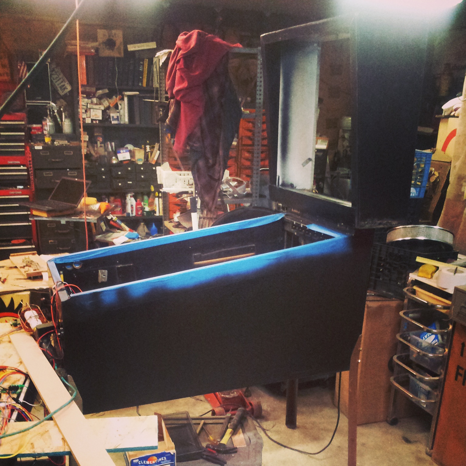
Pinball, pt 2: Cabinet, Playfield Experiments
Some ugly Spring Break artwork wouldn't do, so I spray-painted the cabinet black:
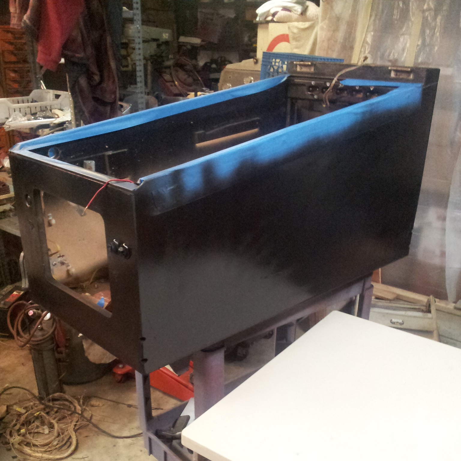
The same went for the head:
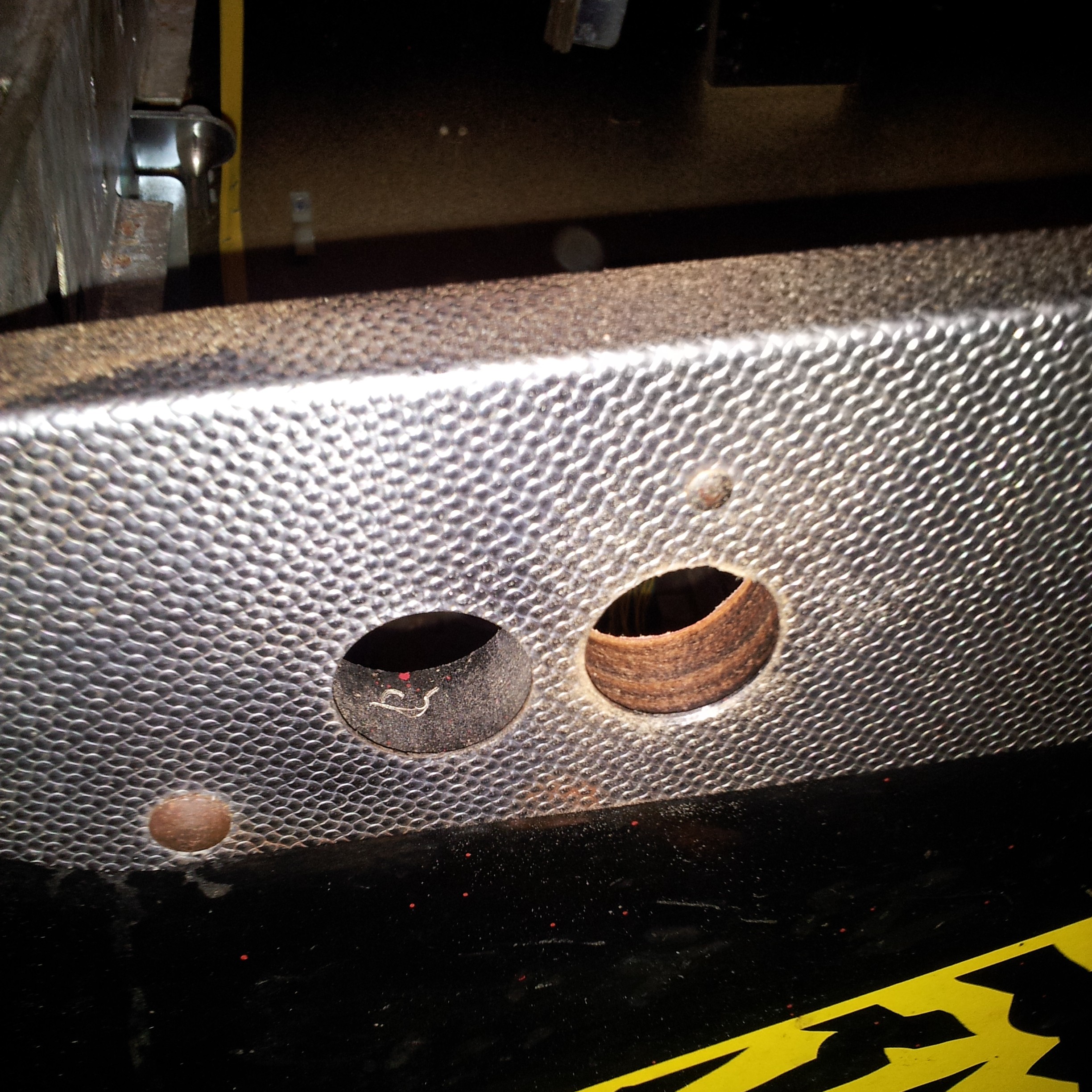
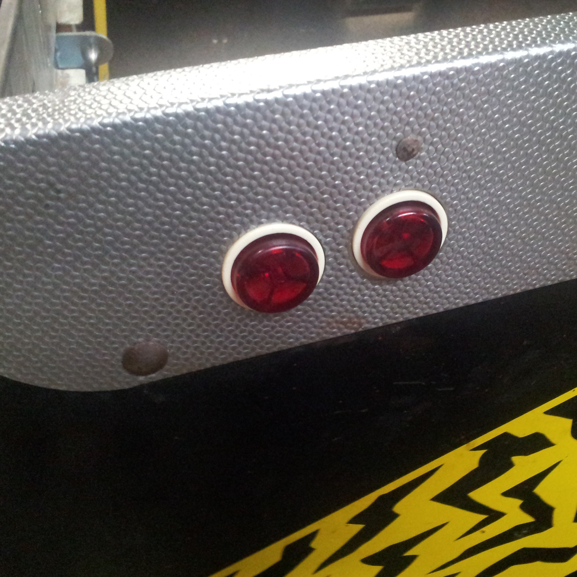
I've never understood pinball machines that couldn't think of a use for more buttons, so I put a second set in:
I picked up a sheet of 0.5" MDF at Home Depot, and lightly drew out my layout
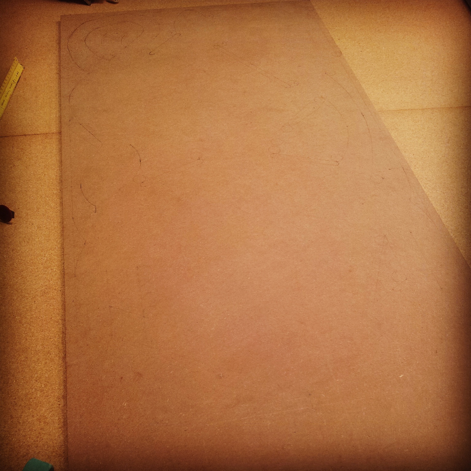

I also used leftover scraps from cutting it to the right size to experiment with mounting components
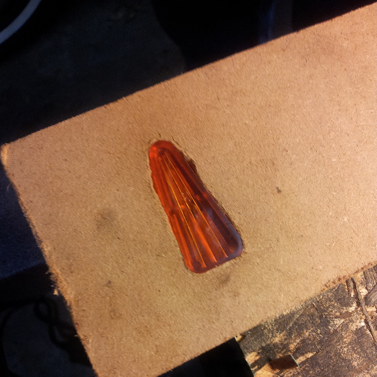
Using a small router and an 1/8" bit, I found that, as long as you go slowly, it can produce workable light insert holes
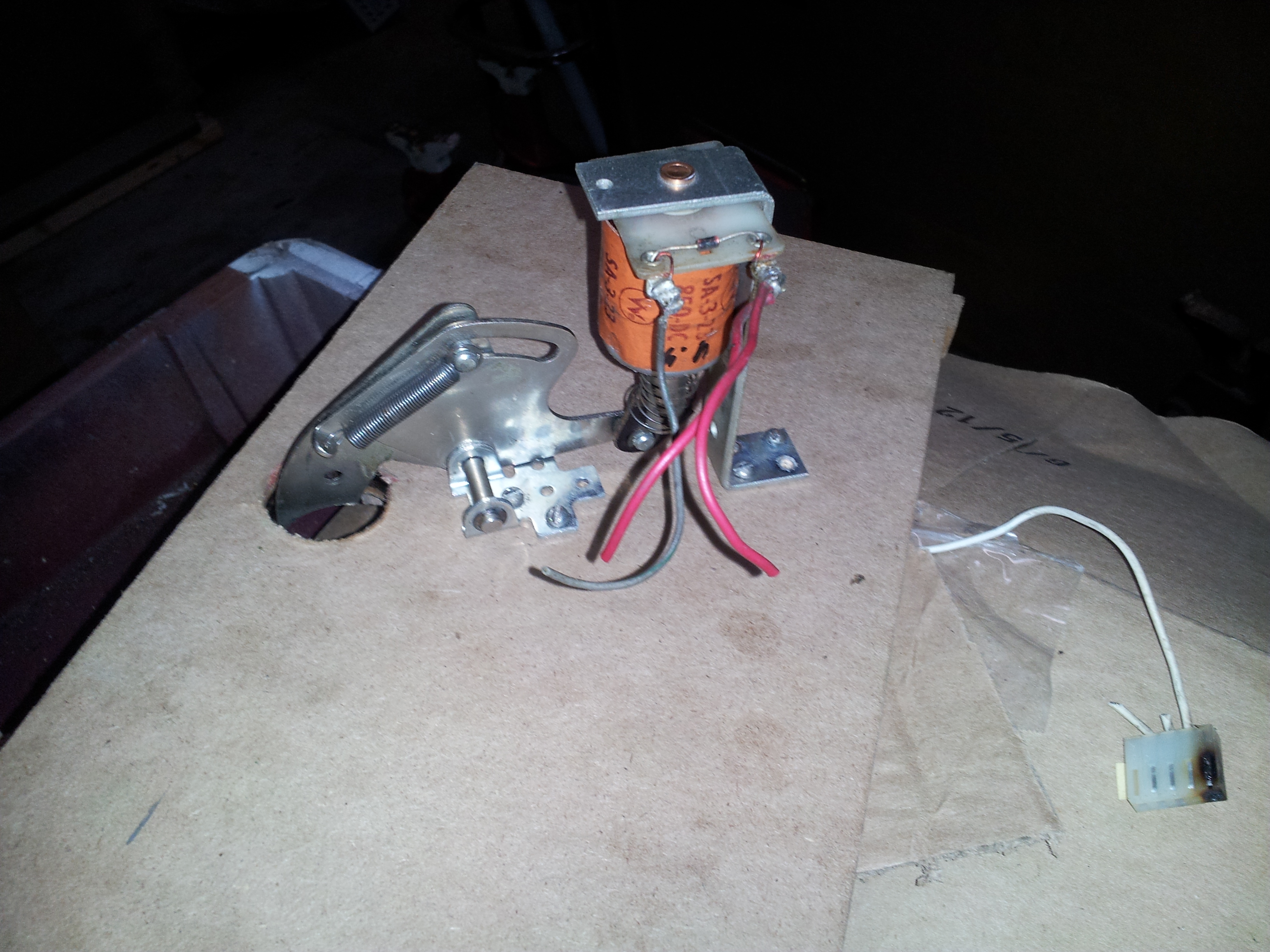
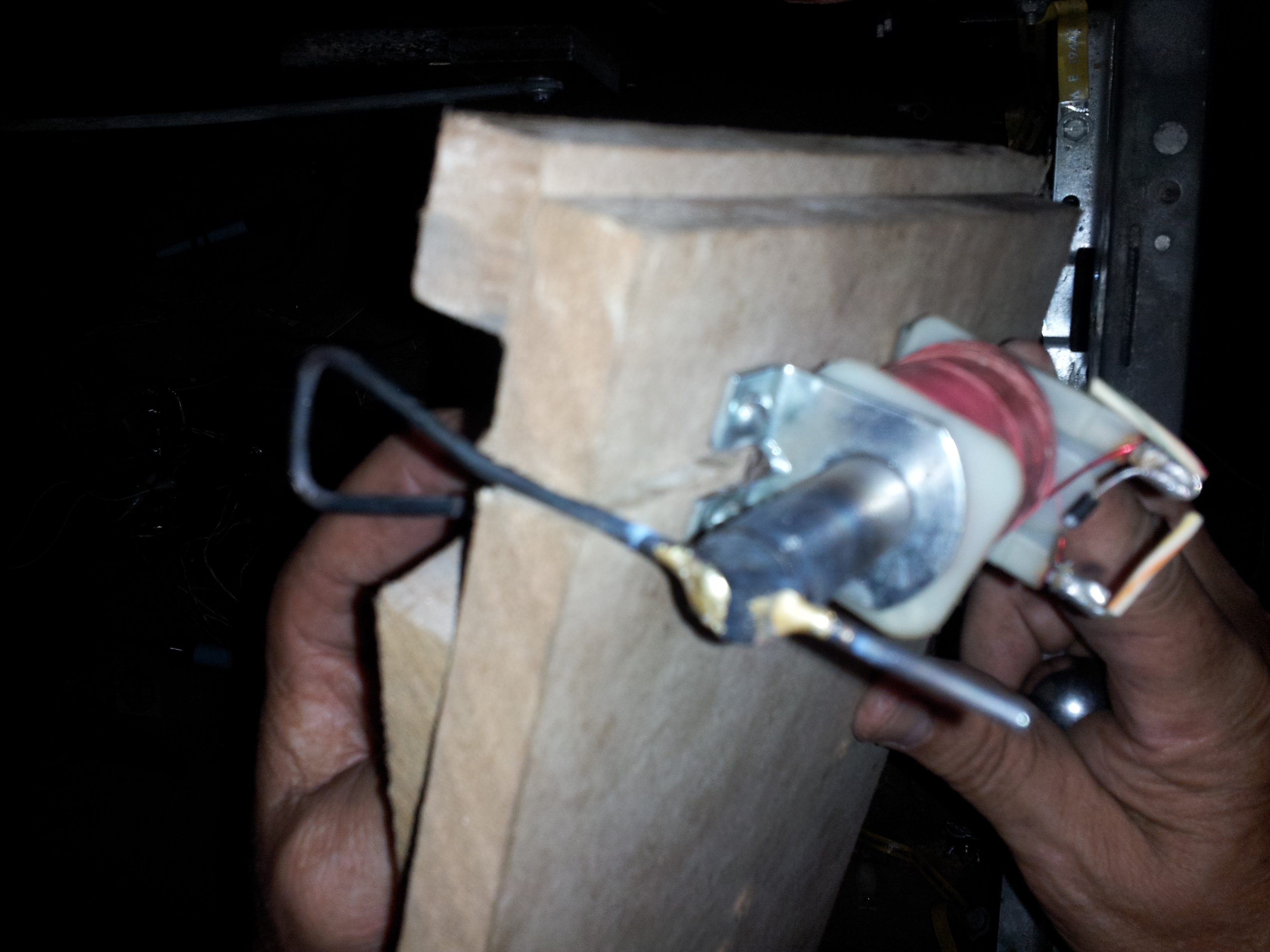
Since I couldn't find any launchers, I made one myself by welding a scoop to a piece of 0.5" iron stock and attaching some plastic to the front to guide it
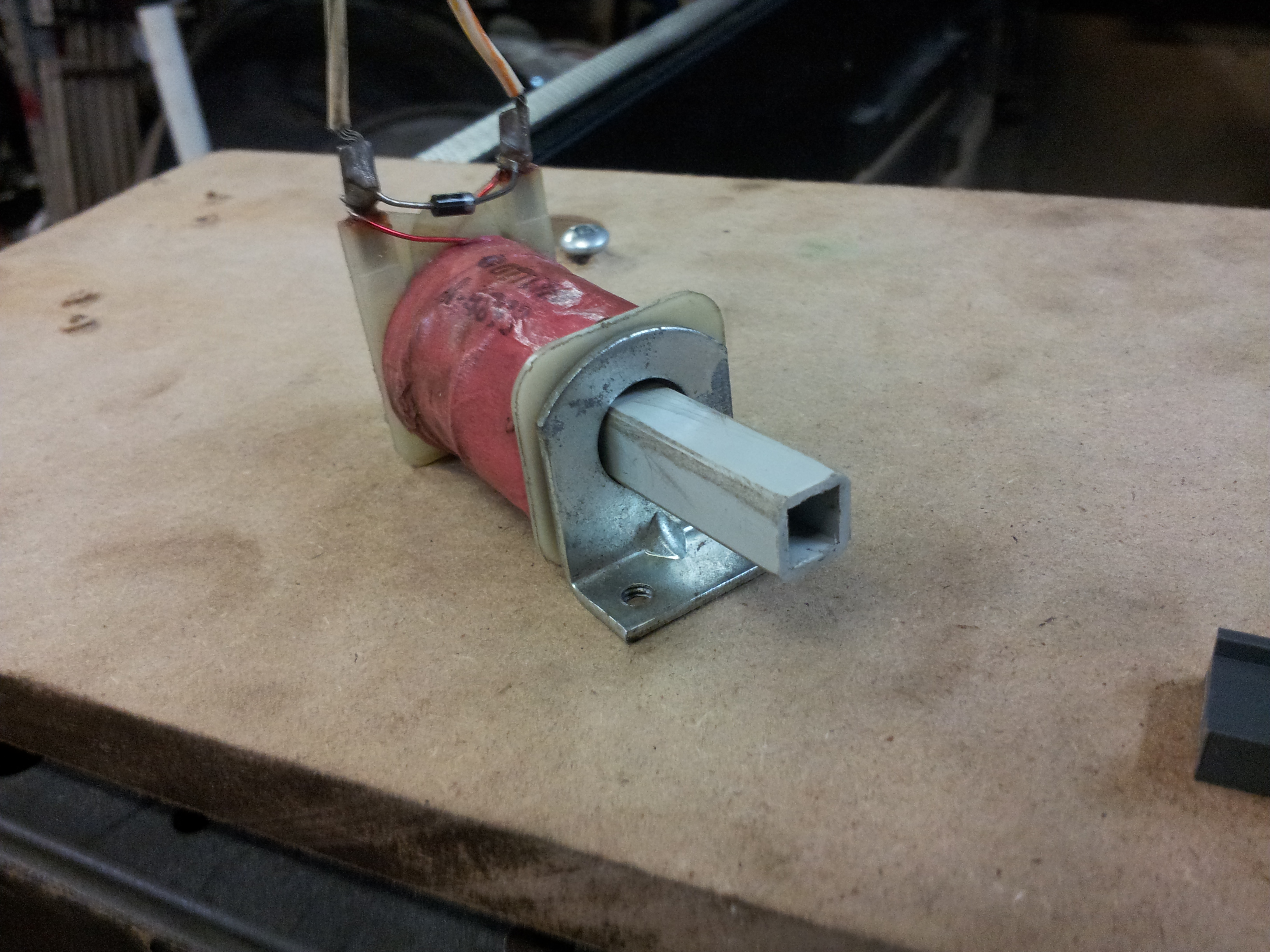
When you power the coil, it pulls the iron stock in, and the plastic guides it through
Pinball, pt 1: Parts
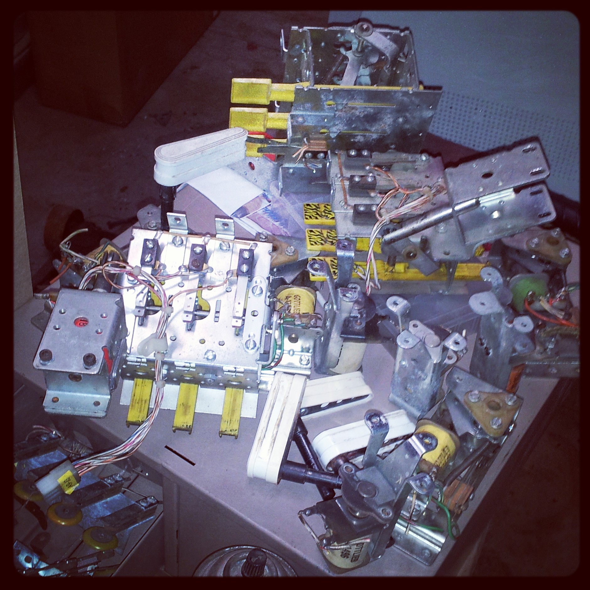
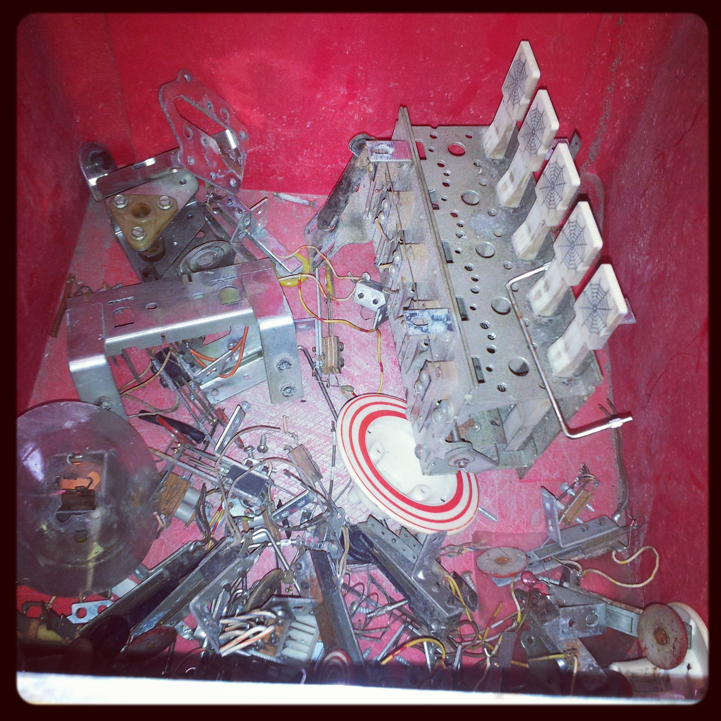
After two trips to the Allentown PinFest, I've managed to get together pretty much all the components I'll need for the build.
I got two boxes of assorted used parts for $20, and a ruined, half populated Spiderman playfield for $30, yielding an assortment of playfield parts:

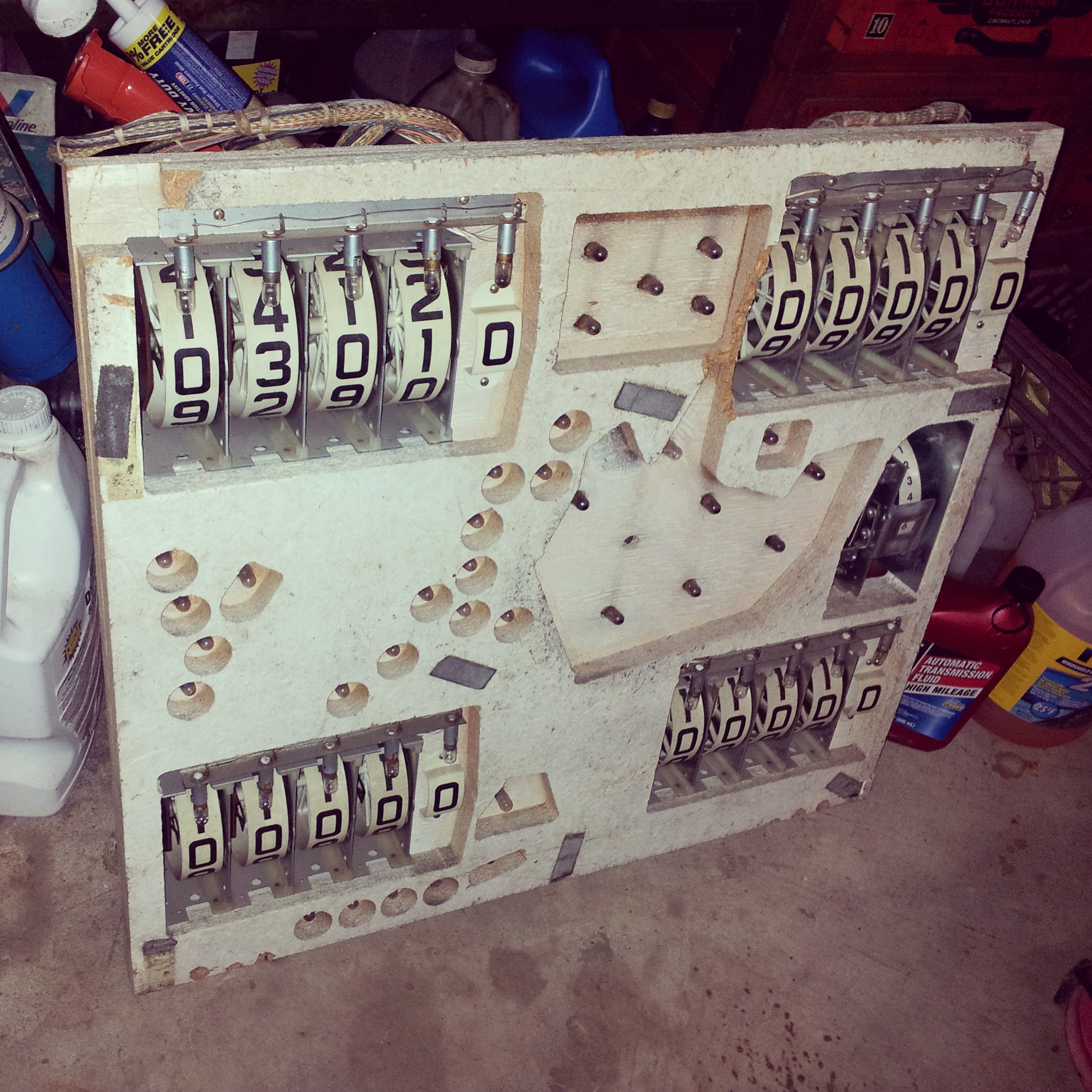
I also bought a head from a mysterious 4 player EM for $20:
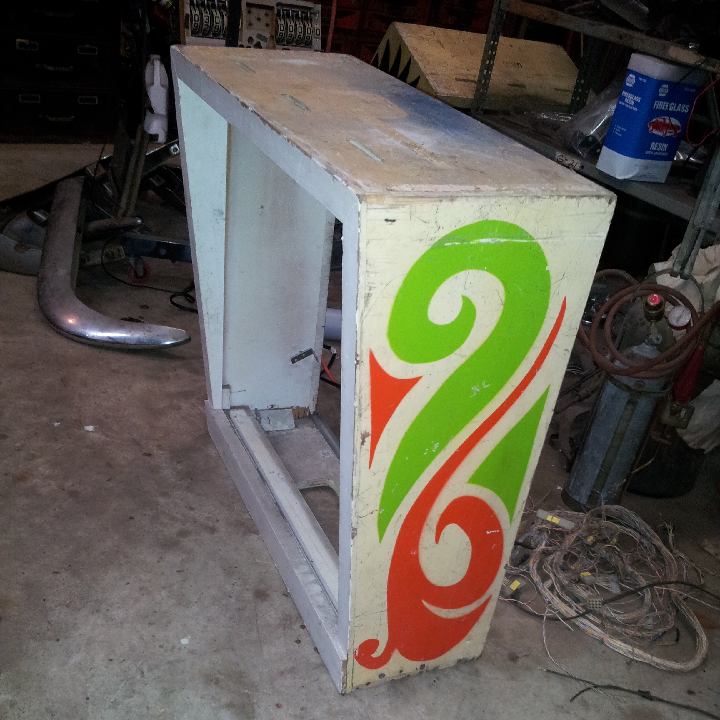

I really wasn't looking forward to the thought of trying to assemble a cabinet from scratch that would work with regular parts, but luckily I found this slightly beaten Spring Break cabinet for $15
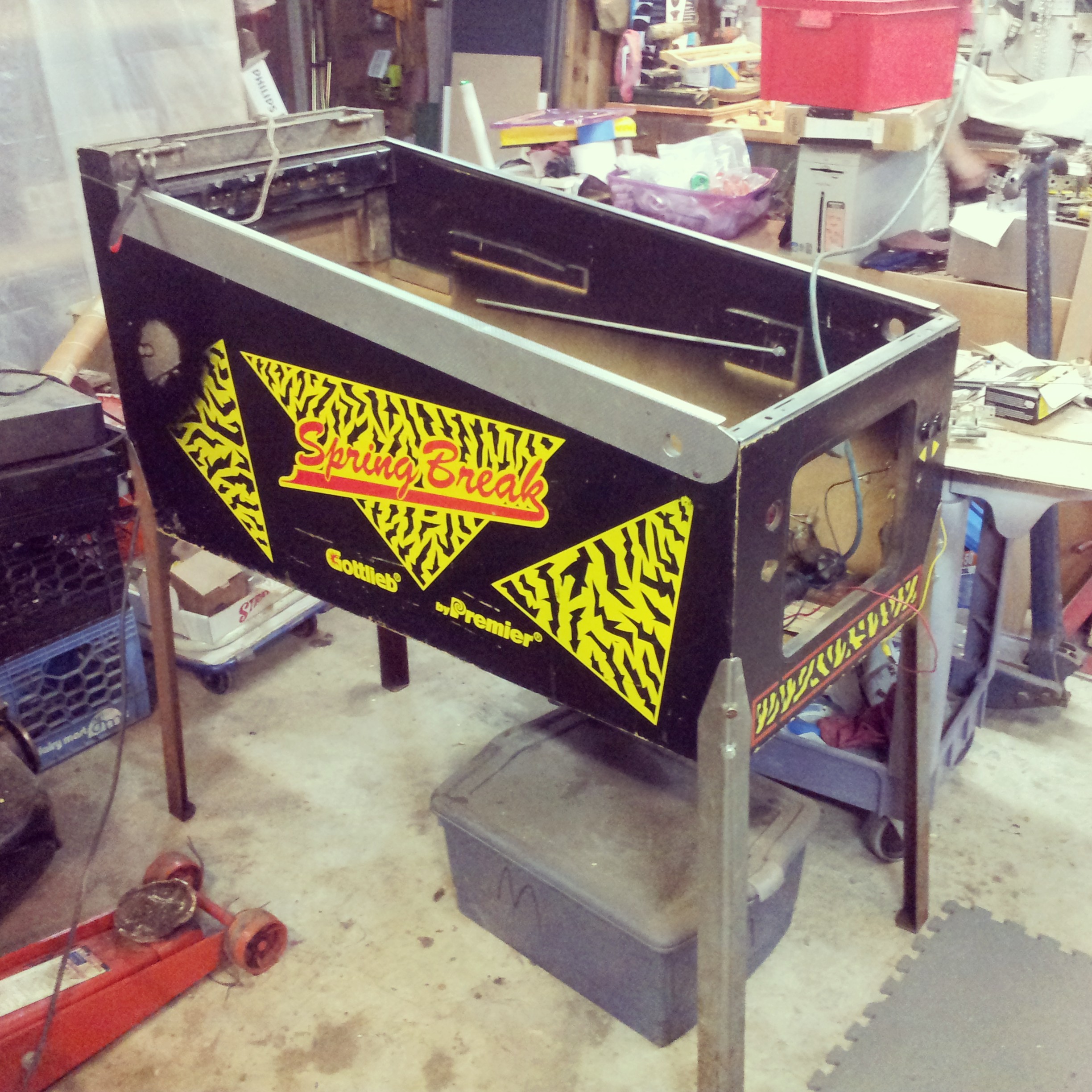
(the legs were separate, another $20)
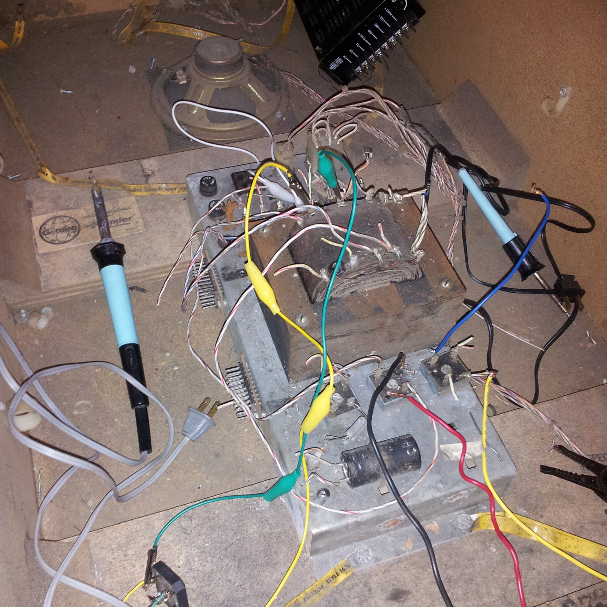
It even came with a working power supply, so I didn't need to worry about finding a 25-50V power supply. I was able to find a combination of taps that put out 28VDC after recification. Most non-EM pinball aficionados seem to think that 50V+ is the way to go, but honestly the flippers seem just as strong on my 25V games as my 50V.
Pinball, pt 3: Electronics
I put in an order to Digikey for $70 (!) of electronics, including some high power MOSFETs for the solenoid drivers:
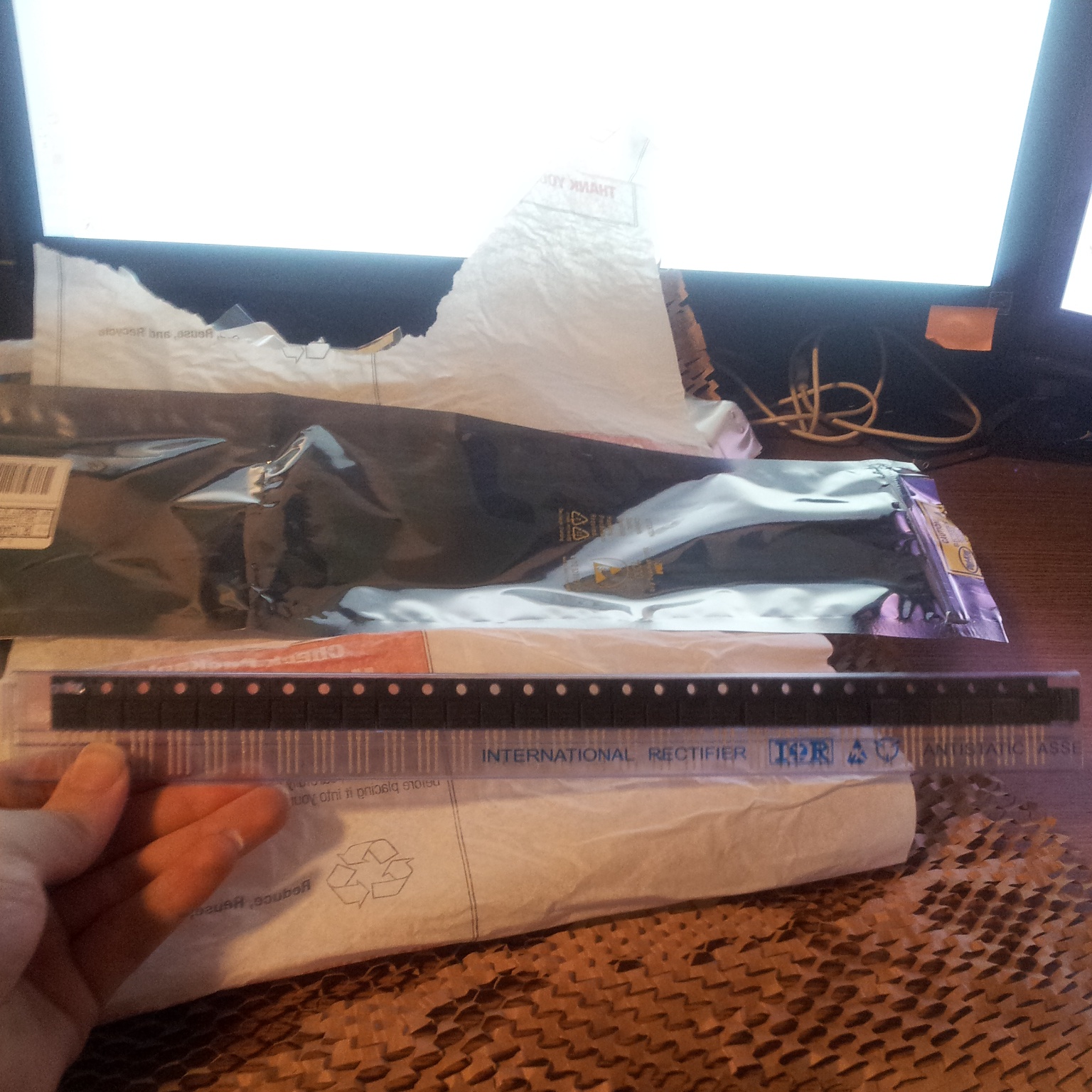
, some serial LED drivers, some serial input multiplexers,

, some parts for making molex connectors,
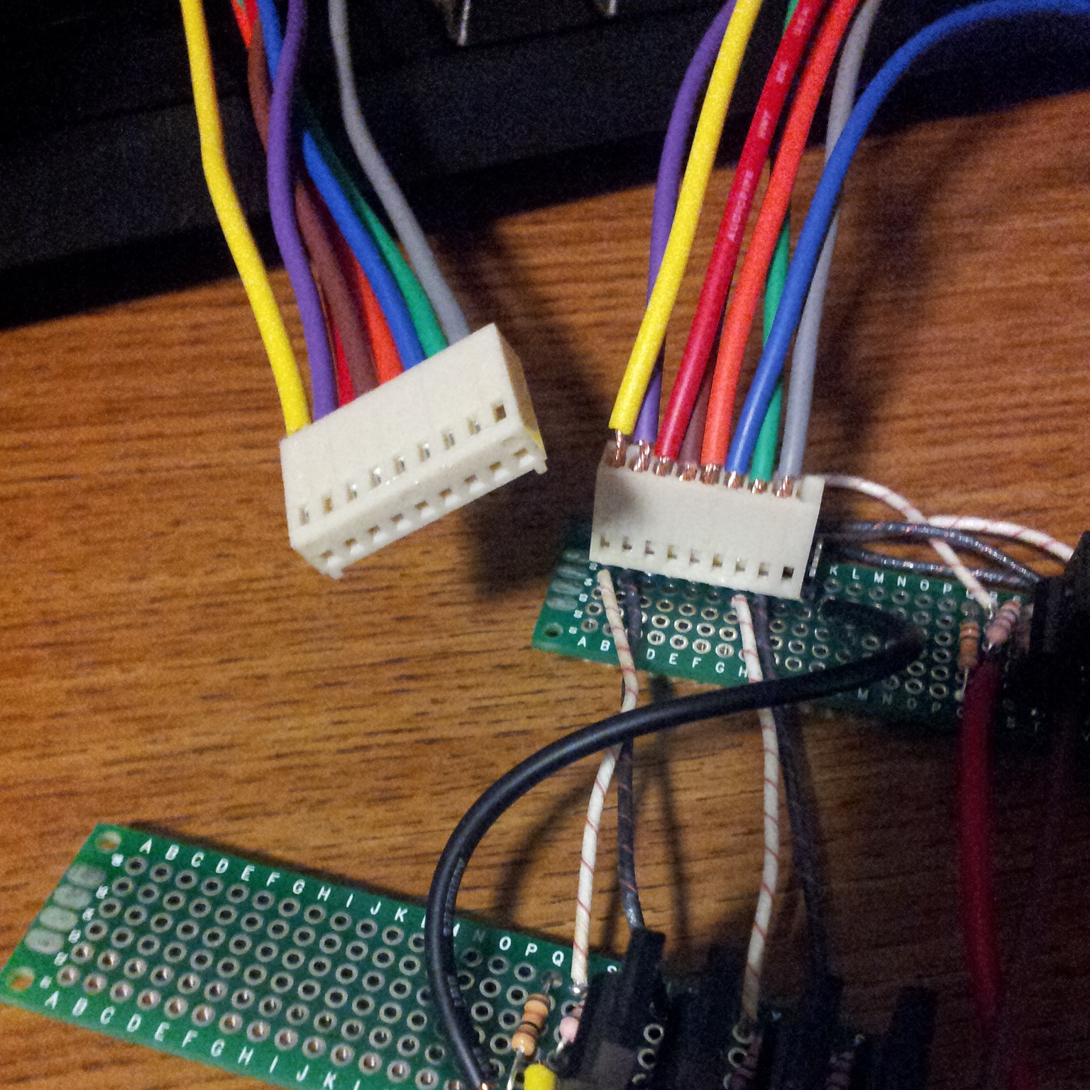
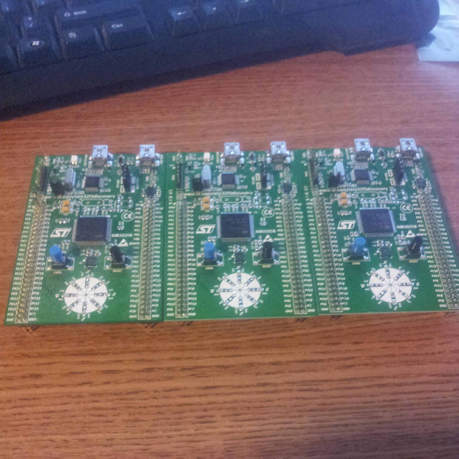
, three CPU boards (basically cheaper, more powerful, lower level Arduinos),
...and a ton of stuff for audio output, including this surface mount op-amp, which turned out to be *really tiny*

I made some nice compact solenoid driver boards
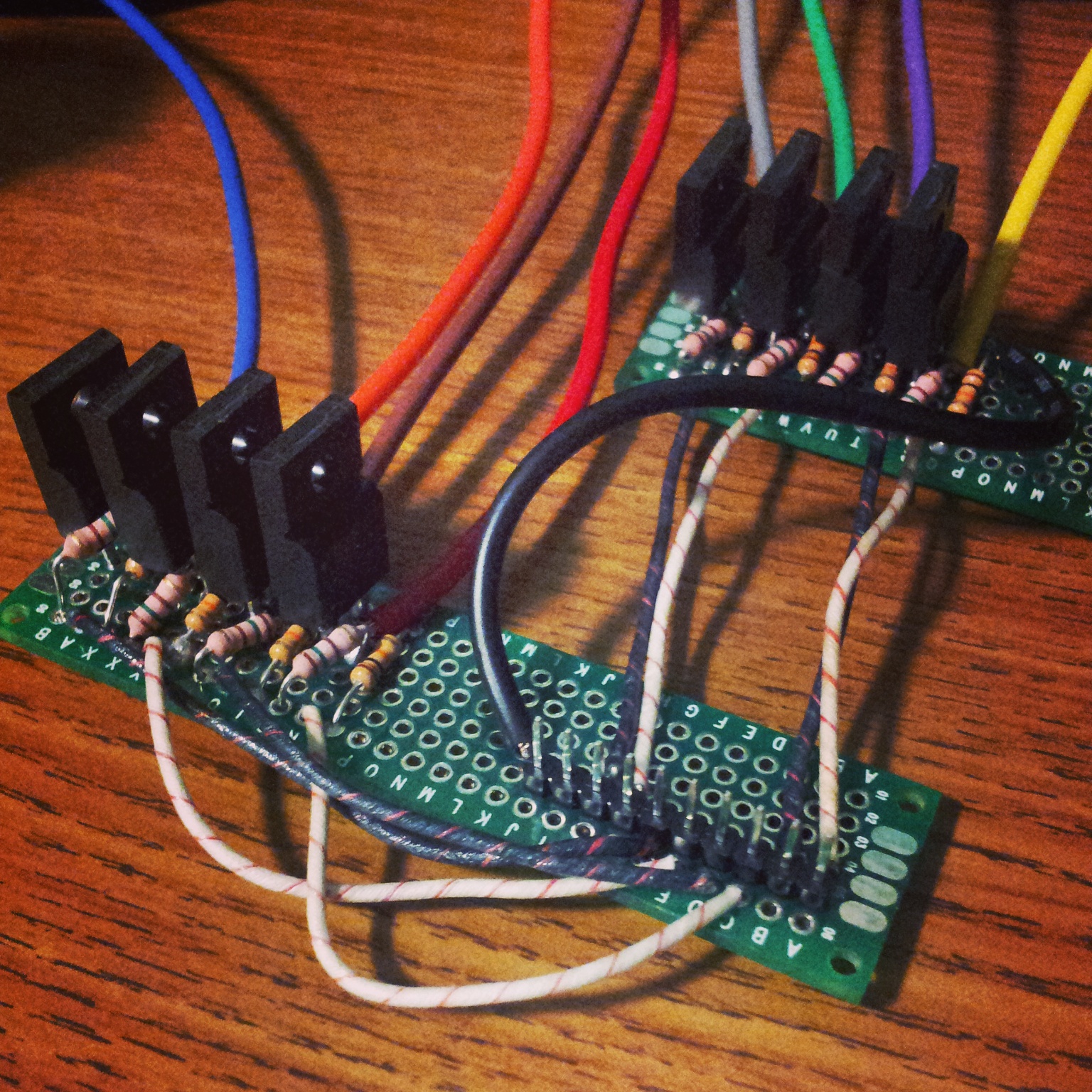
Looking at schematics for actual machines they've got all kinds of weird stuff, however just a MOSFET, two resistors, and a line to the CPU were enough to fire the solenoids just fine. I wish I had some way to turn them off in case the CPU locks up while one is turned on, but I don't know what that would be, and as far as I can tell 'professional' machines don't do it either.